This is the guide that is used in this video to make a DIY cable cam with ODrive / ODESC / ... :
ODrive / ODESC / ... settings
If you have not worked with ODrive / ODESC / ... before, I recommend following my getting started guide.
Configure the basic settings shown in the getting started guide.
odrv0.axis0.encoder.config.cpr =
odrv0.axis0.motor.config.pole_pairs =
odrv0.axis0.motor.config.current_lim =
odrv0.axis0.controller.config.vel_limit =
If you are using the latest firmware version.
odrv0.config.enable_brake_resistor = True
Because this project uses a battery, you can also use regenerative braking.
If you don't have the motor calibration saved using motor.config.pre_calibrated, you have to calibrate at startup.
odrv0.axis0.config.startup_motor_calibration = True
odrv0.axis0.config.startup_encoder_offset_calibration = True
odrv0.axis0.config.startup_closed_loop_control = True
odrv0.save_configuration()
odrv0.reboot()
There are a number of options to get this thing working, if you want basic control, you can use velocity control in combination with an RC PWM input signal.
odrv0.axis0.controller.config.control_mode = CONTROL_MODE_VELOCITY_CONTROL
Set the RC PWM input mode to velocity.
odrv0.config.gpio1_pwm_mapping.endpoint = odrv0.axis0.controller._input_vel_property
If you are using the latest firmware version.
odrv0.config.gpio1_mode = GPIO_MODE_PWM
You can tune the neutral position on your RC transmitter or you can make the min and max not inversely equal (for example use -15.2 and 15).
odrv0.config.gpio1_pwm_mapping.min = -15
odrv0.config.gpio1_pwm_mapping.max = 15
odrv0.save_configuration()
odrv0.reboot()
Another option is to use position control in combination with an RC PWM input signal (with a linear potentiometer for example).
odrv0.axis0.controller.config.control_mode = CONTROL_MODE_POSITION_CONTROL
Set the RC PWM input mode to position.
odrv0.config.gpio1_pwm_mapping.endpoint = odrv0.axis0.controller._input_pos_property
If you are using the latest firmware version.
odrv0.config.gpio1_mode = GPIO_MODE_PWM
odrv0.config.gpio1_pwm_mapping.min = -25
odrv0.config.gpio1_pwm_mapping.max = 25
The position where the motor starts is the zero position, you could also use an endstop to set a new zero position by using homing.
odrv0.save_configuration()
odrv0.reboot()
If you want more options, such as motion planning, you can use the ODriveArduino library.
Schematics
For this project I used a single axis ODESC.
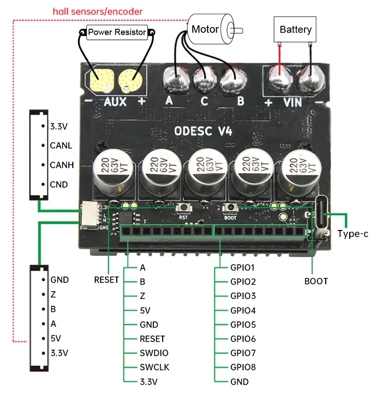
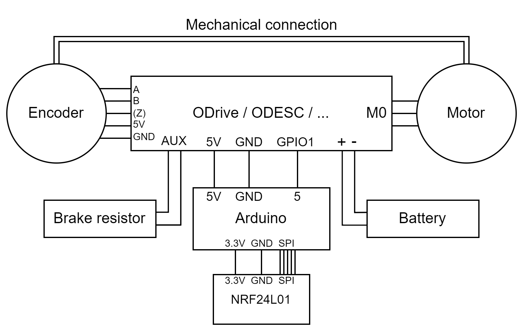
These are the general schematics for the Arduino and RC receiver versions, make sure you have a common ground.
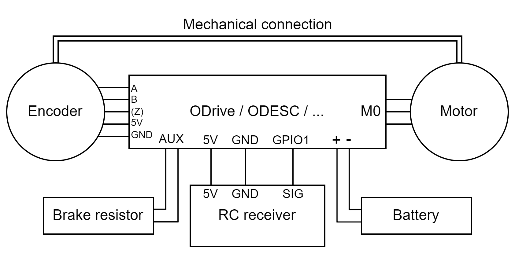
There are a few GPIO pins you can use for the RC PWM input, you can find the pinout here.
You can also use an ODrive or a dual axis ODESC. When using a dual axis board, you could also have 2 spools of wire and depending on the motor rotation directions, the system can move horizontally and/or vertically.